I love my Sony WH-1000XM4 headset. But it bothers me that you can’t charge them wirelessly. So I wanted to change this. Here is the story:
I started by opening up the headphones and located the charging-port. It’s on the right earcup on the backside.
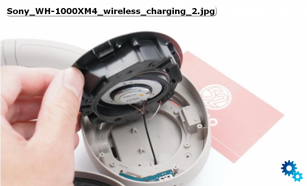
To get to it you have to remove the cushion and the lid which holds the right speaker and a microphone. Be careful not to rip any of the fine cables. You cannot remove the lid entirely because the cables are poke through little holes and are soldered on both sides.
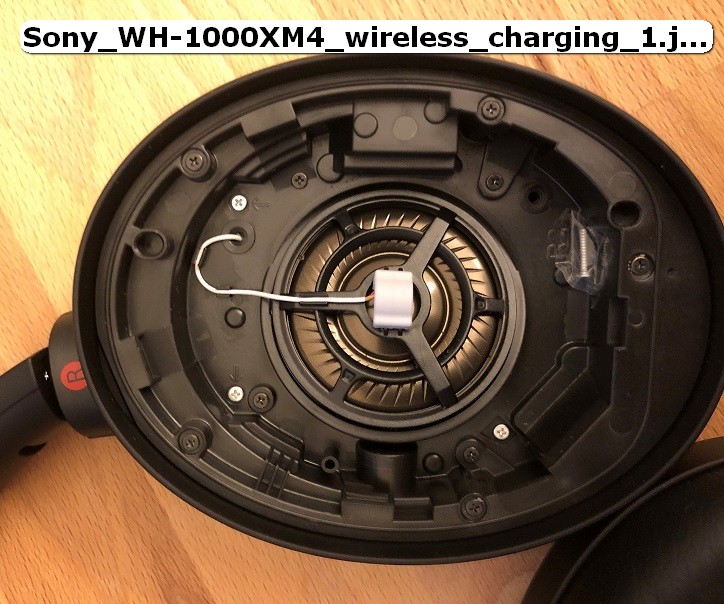
After disassembly of the lid, you can remove the cup on the backside. It was hold by the silver screws that you see in picture 1 (notice that on the picture one screw is not in its designated whole. This is because the picture is from the reassembly process – more on that later).
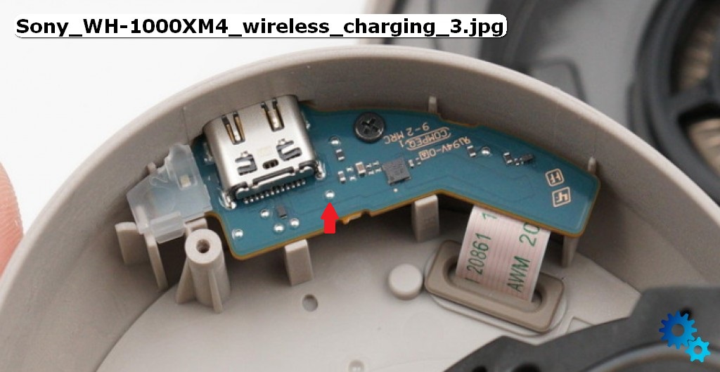
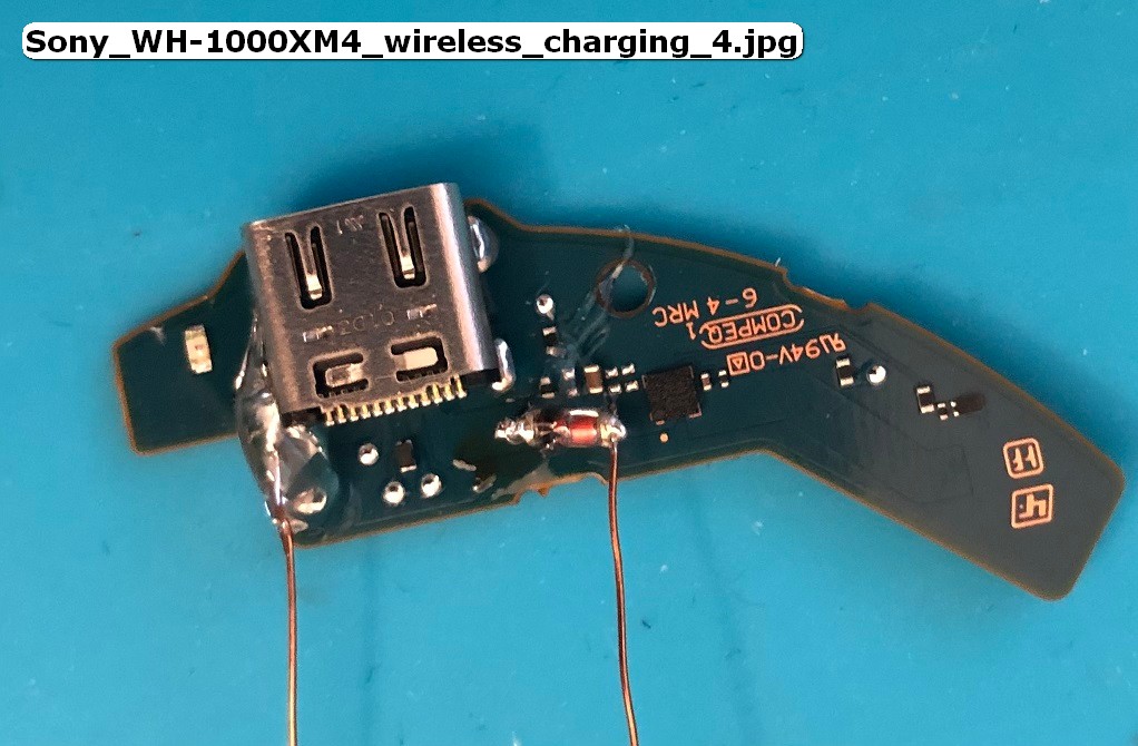
After removing the charging port (picture 3) I measured the exposed pads on the board and found the marked one to have 4.6V while charging with a 5.1V supply. I concluded that this is because of a diode voltage-drop in the chip directly south from the USB-C port. I used this entry point and added my own charging voltage here. For the desired voltage-drop I used a LL4148 100V 0.2A diode. I concluded that the wireless charge pads I used never go above 200mA (even they stated 1A charging – AliExpress-quality). I reenforced the work with some glue because the solder pads from the boards are not very good. You can see the result in picture 4.
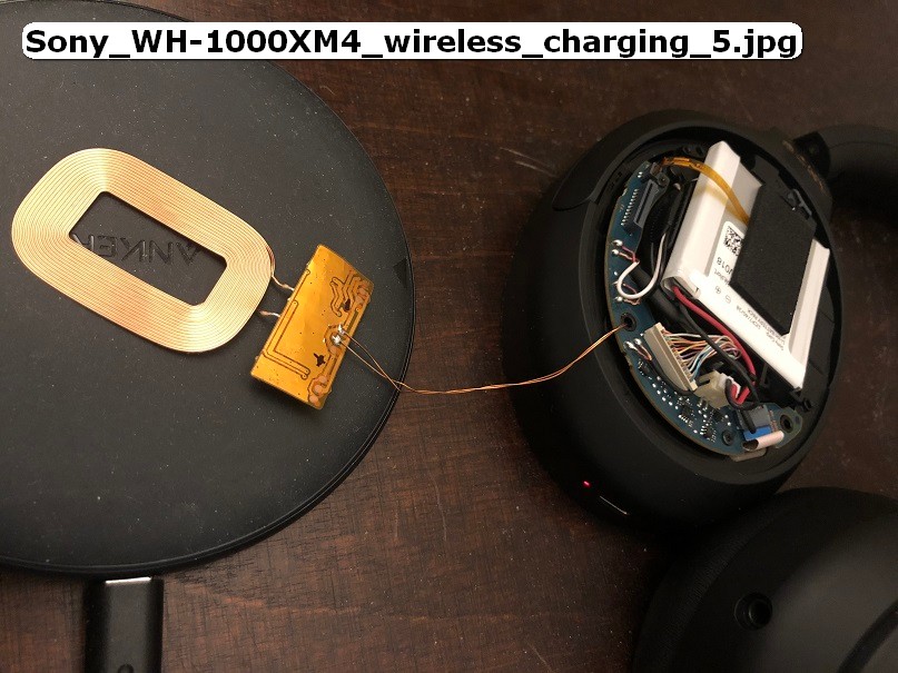
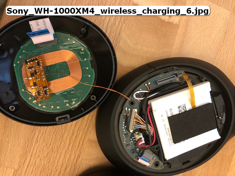
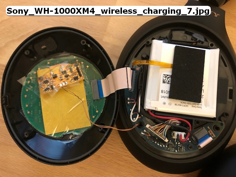
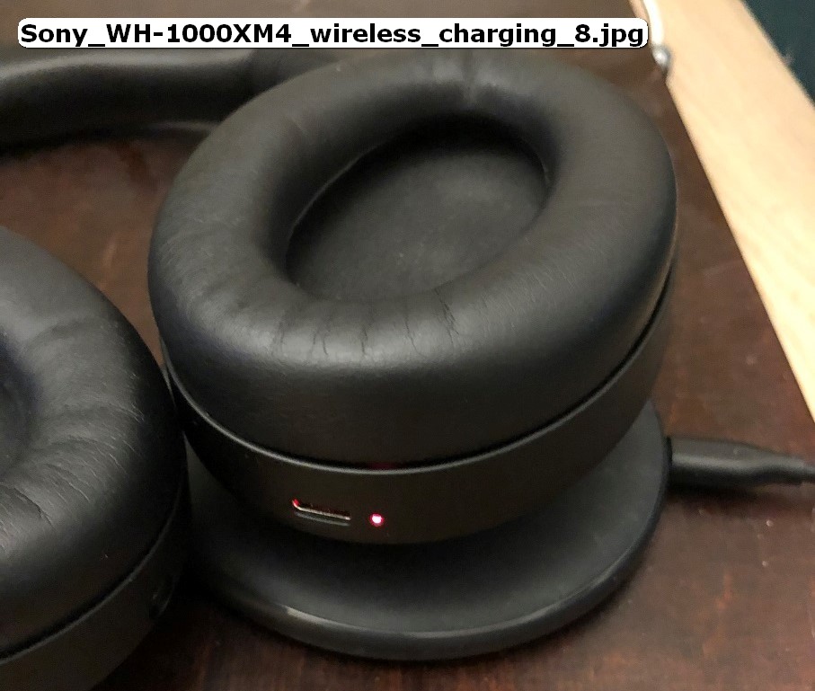
I reinstalled the charging-board and fed the cables through one of the existing screw holes to the backside oh the earcup. There I installed the cheap wireless-charging-circuit and the charging-coil. After testing it – as is – I concluded that it worked barely. I didn’t do inline-measures because it was late but the battery-voltage was raised by the circuit around 100mA while charging via USB-C and 11mA while charging via wireless (picture 5). I stuffed everything in and closed the back cup for a ‘closed test’. This didn’t work at all and I concluded that the gap between the charger-coil and the receiver-coil is too big. I taped the receiver-coil at the back of the cup (picture 6). Notice that there is a circuit-board in the back of the cup. This is for gesture- and volume-control. This will lower the power transceived even further. I hoped that the magnetic field wasn’t too blocked because of this but I was wrong. The charging doesn’t work after this so I put some foil behind the coil to strengthen its effect. This worked barely. You can see the charging-circuit starts up if I place the headphones on the wireless charge pad (picture 8). I also tested that normal charging (via USB-C) and the headphones work properly.
After this I put all together. I left out the silver screw south-east because I fed the wires through this hole.
The next day: I tried to charge my headphones this way. They were at 90%. After 1 hour they were still at 90% but the charging-led was blinking (normal it on or off). I took the headphones of the pad and noticed that the cup was very hot. The circuit shuts itself down probably due to overheating of the battery (see picture 6: the flex cable that go on top of the battery – this is a heat-sensor).
My guess is that the trickle-charging is enough to activate the charging-circuit but not enough to really charge the battery and this messes up the battery (maybe a little shorting though the circuit ?).
I have to investigate this further by charging though my ‘system’ via a bench power-supply so the circuit gets a healthy 250mA or so. And if this worked then I had to add more coil to the charging circuit. But this will be work for another time.
Links:
Pictures from the headset (white version) [here]
Pictures from the headset (black version) – my own
Software for adding labels in pictures [FastStone]
The used chargepads [AliExpress] DO NOT BUY – THEY ARE BAD
